Enterprise networks are always in a state of continuous growth and evolution. With highly demanding infrastructures, large traffic volumes, applications which squeeze bandwidth and network resources, a balance between quality and demand is required. This is where Intelligent Networking becomes critical. One such evolution was Layer 3 Switch!
Evolution of Layer 3 Switching
Layer 2 Switches offer frame forwarding based on the physical addresses (MAC). A network built using Layer 2 switches appears as a Single Flat Address space. Hence a Layer 2 network has limited scalability and flexibility. Layer 2 switches are capable of intra-VLAN communication, isolating data transfer between devices within each VLAN, but they lack the capability of inter-VLAN communication and they cannot route packets between VLANs. This brings in the need for a Layer 3 device.
Routers, operating at layer 3, offer packet forwarding based on logical addresses (IP Addressing). They use dynamic routing protocols to identify best path to a destination. Traditional routers were slower in forwarding packets when compared to switches.
Layer 3 switches were introduced into the market to efficiently perform inter-VLAN routing augmenting all layer 2 functionalities. Layer 3 switches are high performance routers optimized for campus LANs or intranets.
A layer 3 switch is a also referred to as Multilayer switch, since it plays a dual role:
Switch: it performs the Layer 2 functionality of connecting devices that are on the same subnet or virtual LAN at lightning speeds.
Router: it connects subnets or VLANs using its IP routing intelligence which makes it act as a router. It can support routing protocols like RIP, OSFP, EIGRP.
"Simply put, layer 3 switching combines the functionality of a switch and a router, enabling flexibility in your LAN-designs".
Srinidhi Gopal
Lead Embedded Software Engineer
Features of Layer 3 Switch
Packet switching
Route processing
Intelligent Network Access Services, like Quality of Service (QoS), Access Control Lists, ARP, DHCP, etc.
Deployed as backbone of LAN or campus networks
Improves fault isolation when compared to Layer 2 switch
Reduces broadcast traffic volumes
Lower network latency
AimValleyproven track record
Started in 2003, we have delivered over 100 000 deployed systems with customized and varied flavors of the AimOS family to different categories of customers:
AimValley’s Network Software Stack – AimOS has comprehensive support for the relevant standards, with management interfaces and a design suited for the most demanding applications. It is a portable source code implementation designed explicitly to support the scalability, availability and functional requirements of OEMs building devices for next generation networks.
AimOS IP Routing Highlights
Hardware assisted IP Routing
Supports static and dynamic routing protocols
Integrated Free Range Routing (FRRouting or FRR) stack FRR is a free and open source internet routing protocol suite
Uses Linux network stack
Station move support within subnet
Autonomous aging of known-non-active-hosts
Scales well in large networks
Mature and field-tested protocols
Easy to use and integrate with management applications.
Architecture
Application (AimValley application running on the operating system to manage the L3 switch) maintains IP forwarding tables. It ensures that the hardware forwarding tables are in sync with the ones in the software.
Hardware is any L3 capable hardware. It routes IPv4 packets using entries in hardware forwarding tables. In case of miss, the un-routed packets are sent to Host IP-Stack (networking IP stack of an operating system). It handles the un-routed packets from the hardware, performs link-local address discovery using ARP protocol and finally performs software routing of those packets.
Also updates the application of the changes in the IP forwarding tables.
Figure 2: Architecture high level overview
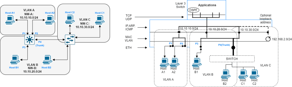
Example Use Case
In general, L3 switch is required to enable communication across different subnets. A subnet can be a LAN where the physical port identifies a subnet; alternatively VLANs can be used to provide a logical sub-division of the IP network.
Considering this, a typical application of a L3 switch is to connect different subnet domains in combination with one or more VLAN switches.
Figure 3: Example network with 3 VLANs
The above figure shows an example network with 3 VLANs (also, we have depicted the IP stack profile of the L3 switch). It presents 6 distributed host systems interconnected by means of VLANs and MAC addresses. The VLANs themselves are interconnected by routing based upon IP addressing.
The L3 switch system itself is reachable via any of the 3 IP addresses, unless special security measures are taken to limit this access. In some systems an extra loopback interface is created. The assigned IP address to this interface can be used as a universal id to reach the system.
In the example above the routing is based upon IP address information which is maintained in the IP routing tables. The routing table defines for each reachable destination the appropriate next hop system (neighbor IP address) and the port to reach this neighbor. The next hop MAC address of the neighbor is determined via ARP. The maintaining of the routing tables is by means of provisioning or by an automated routing protocol.